
Finally I've decided to buy an Android phone... Well, after all, it's like a pocket computer, very useful and lots of fun! Then I started to install tons of apps, and came to this one:
I was excited to try it out and built the ir transmitter described on the site, very simple, and it actually works, but on my Samsung Galaxy I5500 the audio output is really too low to give a good signal to drive the ir leds. So I've decided to build an active driver using a single transistor. Ok, to make it short, it worked and here is the circuit for everyone to try it out. Hope you'll enjoy it!
R1, R2 - 56ohms 1/8W
Q1 - 2n3904
battery - 3,7V (cellphone battery)
Hi Walther,
ResponderExcluirMy phone is Galaxy S,
It seems that PhotoIRmote does not work in my phone.
Can you post the photo of your active IRmitter,
so that I can try to build the same device.
actually, it is very difficult for me >.< !
never do that before.
Regards,
Harry
Hi Harry, I've put a picture of my irmitter, but I guess it won't help much. If you never built electronic circuits, I suggest asking for help to some friend. Soldering components requires some skills and can cause some serious burns... ;)
ResponderExcluirIf you need more information I'll gladly help!
Regards
Walther
Dear Walther,
ResponderExcluirThank you so much for your photo. ^^
Can we use a GP Lithium cell 3V
(eg.CR2016 or CR2032) instead of
the cellphone battery?
Regards
Harry
No problem, they will last far less, but it will work.
ResponderExcluirhi
ResponderExcluirsorry for my bad enflish
i have a pproblem in my country dont exist 56 ohms 1/8 resistence, only 1/4
what can i do?
You can use 1/4W resisters, no problem, besides the size of them...
ResponderExcluirHola, antetodo flicitarte por este trabajo y gracias por compartirlo.
ResponderExcluirTe pediria por favor si es posible que adjuntaras una fotografia del esquema para "NO entendedores" de esquemas electricos.
Tengo los componentes pero no se ni por donde empezar, si fueses tan amable de hacer otro tipo de esquema mas basico, es decir;
Aqui la union de las resistencia con los led y con el transitor, y la bateria.
Siento mucho no poder entender estos esquemas, se me escapan a mis conocimientos.
Gracias de antemano.
Un saludo.
Juan
Good job!!! I suggest to powered it with 3 normal AAA rechargeable battery (1.2 V x 3 =3.6V)
ResponderExcluirThanks, Tzagi! It works with quite any power source, even less than 3.6V, this will mean a shorter range. My tests show that with a cellphone battery the range is of 7 feet (2.1m).
ResponderExcluirThis is a basic circuit, I even didn't calculated the resistor value, I just guessed it and to improve the range added another one in parallel. The pulses from the phone are extremely short, so there's no risk to damage the leds.
I'll try to use higher voltages to see if the range improves.
Juan, voy a publicar un diseño más detallado, tendrás que aguardar un poco.
ResponderExcluirSaludos!
Hi Walther, another question: are you sure that no capacitor is required for isolate the 3.7 volts of the circuit form the audio output of galaxy? Have you tried it? This would improve the smartphone protection from damage.... what do you think? thanks a lot
ResponderExcluirOK, I'm going to assemble your schema... In the original circuit, only Left e Right channel are used from the phone output. In your schema do you use ground and both Left and Right channel together? Can you post some clear photos or a more detailed schema? Thanks in advance!
ResponderExcluirHi Tzagi, sorry I'm coming late to respond your comment. Yes, I think a capacitor would be a good safety measure, I guess a 1uF would do the job. The circuit worked fine, and I had to work on other things, so I still have stuff to check.
ResponderExcluirAnswering your second comment, I used only one channel, but I see no problem connecting both together. I ask you for a little more patience for the pictures, I'll post the as soon as possible.
Thank you for the comments and suggestions!
Hi Walther, thanks for answers. I try to use L e R channel without ground like weGroo team does: the leds are blinking but nothing appens with canon 7D.... at this point I'm waiting for your schema... thanks in advance!!!
ResponderExcluirSorry to sound a noob, But I am in terms of reading circuits...
ResponderExcluirI fancy giving it a go if I could just figure out what is what and where is where...
I see the audio jack running up to the IR Emitters, but I can't figure out what happens after that, 2 other elements? Then battery attached?
Maybe I can't build this? Could I buy one from you pre built? Desperate to get it for this app.
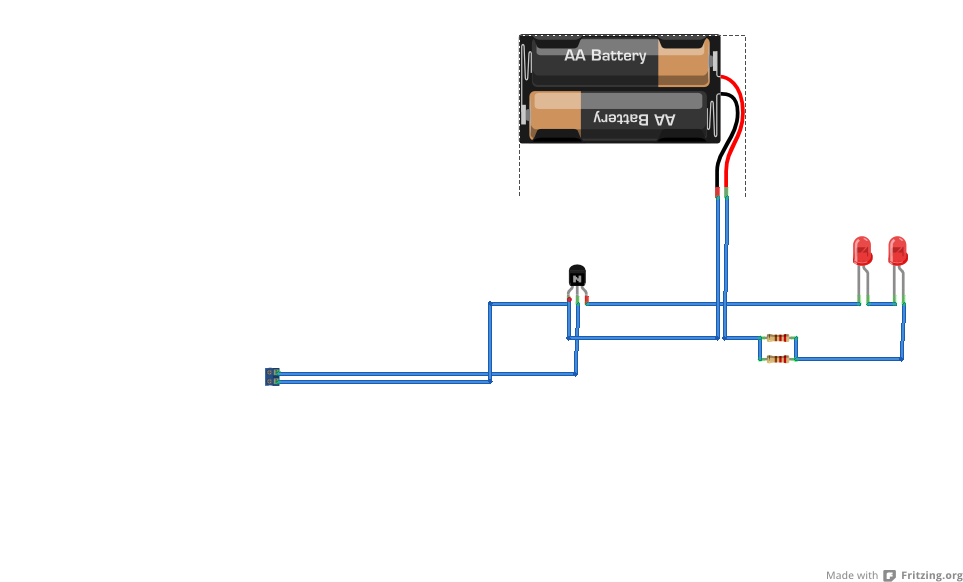
I've added another picture to show how to connect the components. Note that the leds have a flat surface at the base indicating the cathode (http://en.wikipedia.org/wiki/Light-emitting_diode) this is connected to the colector of the NPN transistor (http://en.wikipedia.org/wiki/Transistor). I still haven't included the capacitor between the audio jack and the transistor base, I suggest you do this to isolate the phone from the circuit, a .1uF non polarized capacitor (poliester) should do...
ResponderExcluirHi walter, I couldn't get a 2n3904 transistor, bur I got hold into a
ResponderExcluir-BC 548B
and -2n2222A
Would any of those might work ?
Hi MonkeySensei, almost any NPN transistor will work.
ResponderExcluirhey!... can you sell me one? I'm pathetic at electronics. Just tell me your price, I'd be happy of buying it, and you'd make me a +15% happier man.
ResponderExcluirjgraphix@gmail.com
... porquê duas resistencias em paralelo ?
ResponderExcluir... porquê dois diodos em série ?
o esquema original do emissor passivo usa dois diodos em anti-paralelo ligados a cada um dois canais de audio, o teu jack é mono ou stereo ?
Hola compañero.
ResponderExcluirYo en electronica tampoco soy mu bueno.
Utilizas un transistor y dos leds normales??
Esque ya tengo comprados los led emisores (como en la web del IRmote), entonces no se si podria prescindir del transistor y directamente poner las baterias....
Muchas gracias.
Catching up with the latest comments and questions...
ResponderExcluirSorry ULP and LM Wela, I think that building such a simple circuit to sell (it costs less than 4 bucks...) isn't worth the effort and I'm already short on time with other projects. You may take a look at the links to wikipedia I've posted, they give you the information about the components. My intention in sharing this circuit was to start the idea of an active IR transmitter, hoping someone would come with ideas to make it better. I suggest you to look for help with some friends that have a soldering iron. ;)
Thank you for your interest in this, as soon as I have more time to work on this I'll put more pictures and try to explain it better.
JpontoP,
obrigado pelo interesse! A questão das duas resistências é para aumentar a corrente que passa pelos diodos de forma a intensificar os pulsos emitidos aumentando o alcance que passou a quase 2m. Pus os diodos em série, pois usando o transistor eu tenho corrente passando em um só sentido, no circuito original a corrente é alternada. Utilizo um jack stereo, mas apenas um canal é utilizado (tanto faz qual seja), pode-se ligar os dois canais juntos, mas nã é necessário. Eu não pensei em ligar um capacitor entre o jack e o transistor, é bom isolar o circuito do celular para proteger a saída do aparelho. Um capacitor de .1uF (microfarad) resolve, ainda não testei, estou sem tempo para isso no momento. Agradeço novamente e espero ter ajudado.
ÞĦΨЯΘ§,
Hola, que tal? El transistor es NPN y los leds son IR (infrared). En el circuito original, ellos son conectados directamente, la funcción del transistor es de amplificar los pulsos de áudio del cellular. Conectar las bateroas directamente podria dañar-lo
Gracias por tu interés!
Parece que o teu circuito embora funcione pode ser optimizado:
ResponderExcluir- em vez de 2x56ohms pode usar-se 1x180 (220 parece-me mais popular com pouca diferença no resultado final) e para quem se preocupe com isso pode usar R de 1/4 em vez de 1/8W;
- e na verdade os dois diodos em serie são completamente redundantes, pelo que um bastaria;
- agora sobre o jack stereo vs mono a coisa complica-se no site do PhotoIRmote há varias observações dos criadores do software sobre a necessidade de haver dois diodos em antiparalelo para que o sinal de ambos os canais de audio funcione.
Pergunto: o que é que consegues comandar com a tua montagem ?
De qqr modo acho o teu 'modelo' inspirador.
Oi JpontoP,
ResponderExcluiros resistores eu comecei usando um só de 56ohms e depois acrescentei o outro, assim aumentei o alcance do aparelho, coloquei dois diodos em série para ter um facho mais consistente, um só funciona também, mas fica meio difícil de acertar o "alvo". Já quanto ao sinal de áudio e usar os diodos em anti-paralelo, isso não fez muita diferença para mim, consegui controlar tudo certinho.
O objetivo desse circuito era testar o programa e funcionou, postei para que a turma da rede experimentasse e desse sugestões, ou seja, pus a pulga atrás da orelha, né? he he
Valeu pela discussão construtiva, é assim que a coisa funciona!Questionamentos ajudam a melhorar a idéia. Se você tiver sucesso com o circuito e fizer melhorias avise que o pessoal vai gostar!
Obrigado pelas sugestões!
Certo Walther,
ResponderExcluirPelo que percebi na pagina do photoirmote, para comandar com sucesso os equipamentos (maq fotográfica) é necessário o sinal dos dois canais de audio.
O q vou tentar fazer é uma amplificação para cada um dos diodos do modelo deles (inspirado no teu).
Mas como sou muito casmurro e só uso material usado vou ter que encontrar dois transístores iguais em algum equipamento por aí :D Não tenho pressa
Experimentaste com baterias mais pequenas ?
Vou aguardar os resultados! Eu testei com uma pilha botão e funcionou bem, mas a durabilidade certamente cairá, o consumo é elevado para esse tipo de bateria. Uma dica, praticamente qualquer transistor NPN funciona, PNP também, mas eu só tinha esses disponíveis então...
ResponderExcluirQualquer coisa entra em contato.
Hola Walther, compre todos los elementos que indicas y lo arme segun la grafica pero no funciona. Mi problema es que no estoy seguro de que conectar al Jack estereo, podrias indicarlo con mayor exactitud. Gracias
ResponderExcluirHola amigo, podrias mostrar una imagen de como conectas el Jack Stereo al circuito, no se entiende bien. Gracias
ResponderExcluirPuedes conectar a uno de los dos canales o los dos, no hay problemas con esto.
ExcluirPerdon por la respuesta tardía...
Este comentário foi removido pelo autor.
ResponderExcluirWhat should I do if the audio output is to low for the transistor collector?
ResponderExcluirI tried the 3.5mm cable in my phone and got 0V when no sound is playing and .1mV when there is sound.
I also tried the 3.5mm cable in my laptop and got .2mV with no sound playing and anything in between 1mV and -1mV when sound is playing.
I connected the 3.5mm cable to the transistor just like the picture above except I replaced the 2 IR LEDs with 1 red LED, and removed the resistors.
The led does not light up when I play any sound and when I connect my multimeter it does not measure any current. So I believe that the audio output is too low for the transistor.
Any help?
Well, I tested this circuit with my Samsung Galaxy S, and it worked fine. Maybe you could try using two transistors to get more gain.
ExcluirSorry for my sloppiness, friends, I've been really busy lately. I promise, I'll add some updates to this topic soon.
ResponderExcluirpuedes hacer un esquema con 2 transistores y montar donde conectas los cables en el jack que se conecta el movil.
ResponderExcluirgracias
Amazing post in this blog. Hope more people reaching your blog because you are sharing a good information. I noticed some useful tips from this post. Thanks for sharing this.......... Electronic equipment manufacturers
ResponderExcluirHello Sir,
ResponderExcluirWell Come to you. I really appreciate you for all the valuable goods that you are providing us through your blog.
I have plan to buy a ISP In system programming from equip-test.com. Equip-test is a largest manufacturer of in-circuit and modular functional Test Fixtures, including, ICT Fixtures, Flash Fixtures, Functional Test Fixtures, Rf-Fixtures and many more electronic products at reasonable prices in Europe and have more models. Can you suggest me, which one is better for me and my friends.
Thanks a lot!
Pouls
ISP In system programming
Can you tell me what the little grey box is on the left side of the wiring illustration?
ResponderExcluirhttp://4.bp.blogspot.com/-PrKs-HXQqcc/TnNMfkfkUkI/AAAAAAAAXtY/cfVJOZ8wj54/s1600/irmitter_bb.png
I understand the other components but I don't get what this is.
Thanks!
It represents the stereo plug to the phone, I should make a better schematics...
ResponderExcluirno consigo que me funcione. podrias ayudarme?? porfavor
ResponderExcluirHoy en día la tendencia de los teléfonos i realmente se va muy alto. Me gusta mucho el diseño del circuito en este blog. Intercambio interesante.
ResponderExcluirEficiencia energética
Lcd Tv Repair
ResponderExcluirVery Nice Post.
Good information nowadays.
Thanks for sharing with us.
i build the above circuit exactly but it didn't work, my mobile is Samsung Galaxy Note 1.0, i checked the volt that actually out from the mobile headphone socket when running the PhotoIRemote Test, it between 0.4 when my voltmeter is set on DC Volt 200m. so how to make it work!! i also test it on Galaxy S2
ResponderExcluirCheck if you haven't inverted the terminals of the transistor. The circuit is pretty sensible, it should work for almost every phone. Also check for your volume settings on the phone.
ExcluirEste comentário foi removido pelo autor.
ResponderExcluirSomeone please upload a video of how to do this .... He searched everywhere
ResponderExcluirNo problem, ams patil, be my guest.
ResponderExcluirThe app for smartphones had been improved and there's a new site about it: http://www.wegroo.com/photoirmote/
ResponderExcluirWalter lo he conseguido pero la distancia respecto a la tv no es de mas de 35 centímetros. Como podría ampliar esa distancia a por lo menos 3 metos
ResponderExcluirLas resistencias eran de 560 o 56
ResponderExcluirI will recommend anyone looking for Business loan to mr benjamin who helped me with Four Million USD loan to startup my business and it's was fast When obtaining a loan from them it was surprising at how easy they were to work with.The process was fast and secure. It was definitely a positive experience.Avoid scammers on here and contact mr benjamin On. 247officedept@gmail.com . WhatsApp...+ 19893943740. if you looking for business loan.
ResponderExcluir